Wednesday, November 25, 2009

Microchip 16 bit design contest

Microchip/Circuit cellar have announced a 16 bit embedded control design contest - the idea is to promote the use of the dsPIC family of controllers.

Microchip is giving out a generous sample of components to the contest participants - here is what I got:

p1

p2

I find the ENC28J60 device very interesting - it’s an ethernet controller using which your microcontroller can communicate over an ethernet LAN!

Any good ideas to create a prize winning entry?

USB Interfacing with GNU/Linux and PIC 18F2455 - Part 3

Completed interfacing an LCD panel with the USB PIC, thanks to Anish. We are still not able to get interrupt URB’s working properly - except that, everything is OK.

usbdev

Coming next: A comprehensive tutorial on developing USB gadgets with GNU/Linux and PIC! We hope to get it published as an LDP HOWTO.

USB Interfacing with GNU/Linux and PIC 18F2455 - Part 2

It’s no wonder that there are so few complete resources on writing USB firmware on the net - there is only one word to describe the process - `tedious’.

The last few days have been spent reading USB Complete - this is the only good book available to help you get along … it’s extremely well written. This book, combined with the code ofPUF framework seems to be the best combination for getting started. Another great resource is the code written by Bradley A Minch available from here. I prefer the PUF code because it’s better structured - but there seems to be some trouble with the configuration bit definition in it.

Our development environment is now stable. The programmer, `odyssey’, is working perfectly and SDCC + gputils seems to be generating correct code. Unfortunately, we were unable to get PUF running on our 18F2455. So we began taking out bits and pieces of code from PUF and started testing them independently. We were able to go as far as initializing endpoint 0 and getting an OUT transaction on it. Now the trouble with USB is that it has a tricky state machine - the way you handle the current transaction depends on what the previous transaction was. You will soon reach a point where you won’t be able to test things with 10-20 lines of code - you will have to have the whole state machine running smoothly. So yesterday, Anish `cleaned up’ the PUF code taking out a lot of things which were not going to be useful for us at present but keeping the core intact. And, magically, everything started working. Enumeration was succesful and we have endpoint 0 ready to accept control transfter requests!

Understanding Microchip’s description of the working of their USB SIE (Serial Interface Engine) is another headache.

Now we have to get some `vendor’ requests working and maybe configure another endpoint to do interrupt transfer. I will think of writing a proper tutorial after that.

USB Interfacing with GNU/Linux and PIC 18F2455 - Part 1

Even though USB has become wildly popular, there are not too many resources on the web which gives you a tutorial introduction on how to go about developing USB peripherals and controlling them with GNU/Linux. Anish and myself have started work on creating a simple USB gadget - we intend to document the process thoroughly so that others can do the same with the mininum of effort.

Choosing the proper microcontroller and setting up a decent development environment is the first headache. When it comes to USB aware uC’s, there is not too much of a choice - it seems that the USB PIC18F devices are the only ones commonly available in India. We purchased a few PIC18F2455 devices from Future Techniks. These are 28 pin devices which are USB 2.0 compliant. Now comes the issue of finding out a proper `burning’ software and hardware. The trouble is that most of them are written for Windows. Anish was succesful in running Free PicPgm under Wine. But I am not satisfied until I find a a 100% GNU/Linux solution. We spent lots of time exploring various possibilities which included using bootloaders - Microchip has an `official’ bootloader whose working is fully documented. The trouble is that there is no GNU/Linux frontend for it - so we had to write a Python program to parse Hex files and deliver it to the bootloader in the proper format - the effort was abandoned midway because we thought it would take some time to test the code thoroughly.

Luckily, we discovered Odyssey, a very well written program for downloading code to PIC devices. It works well with the classical David Tait high voltage PIC programmer. Only trouble was creating two config files - one which describes the hardware (which parallel port pin controls which pin on the PIC) and another one which describes the PIC18F2455 device (device id, config bit masks, amount of code memory etc). The programmer has been working reliably for the past two days.

Now comes the issue of choosing development tools - PIC’s are usually programmed in assembly - they have a bizarre architecture which makes them unfriendly to C compilers. But Microchip has brought out a few changes in the 18F family - it’s said that these changes make the processor more compiler friendly. Anyway, I wish to avoid assembly coding as far as possible. The only freely available C compiler for the PIC’s is SDCC which has support for PIC18F devices. We used a version of the compiler bundled with PUF - the PIC USB Framework. It seems the compiler is not very good at generating compact code - but let’s hope it does a good job generating code! We did a few tests yesterday - and they were OK. But the linker, `gplink’ seems to be having a bug (is it a bug - not sure). SDCC lets us declare arrays in program memory space by using the `code’ directive. Thus, we can do:correct

code unsigned char a[] = {0xe, 0xd, 0xe, 0xef};

This places data in the `code’ section of the resulting object file. The linker, `gplink’, objects to this and generates an assertion failure when it tries to produce a list file.

Friday, November 13, 2009

Classic LED 7-Segment Displays

Just recently I have been addicted to old LED displays as they are small and bright and I love the classic look. We can see them in vintage calculators and vintage led watches. However these displays consume significant amount of power, so they are not used in watches and calculators anymore. As they are replaced by LCD, these LED 7-Segment displays are not in production anymore and difficult to obtain.

Now, I have 2 models of the classic LED 7-Segment as shown in the picture below: HP 5082-7414 from HP is on the left. It’s a 4-digit Red LED 7-Segment very nice for wristwatch. The one on the right is an 2-digit Red LED 7-Segment from an unknown maker. It can be used in a wristwatch too (with a little bit bigger case).

LED 7-Segment Display HP 5082-7414

Based on my inspection, I have made symbols for these displays with Eagle 5.4.0 free version. The displays are common cathode and the symbols are below

LED 7-Segment Display HP 5082-7414 schematic

The PCB footprints are as the following (DIP 12)

LED 7-Segment Display HP 5082-7414 PCB footprint

I have made simple clocks using these displays and PIC16F887. The real thing looks much better than the photo. The displays are bright red and sun light viewable. Very COOL!!! They are on my computer desk and I love to see them very often.
bubble-7-segment-clock

LED 7-Segment Display HP 5082-7414 clock

LED 7-Segment Display HP 5082-7414 digital clock

Each clock consumes about 0.25W (50mA, 5V) when the PIC16F887 operates at 250kHz (display refresh rate is about 61Hz). The amount of consumed current can be reduced significantly if I use some current limit resistors. But the displays will be dimmer than without resistors. I will try to use PWM for reducing the power consumption as I don’t want to put 8 resistors into my design. The schematic/PCB and firmware including source code in MikroC will be made public once I have complete all of the designs. I will even have kits for sell if my time permitted.

Small LED dot matrix development board

I was very busy for the past two months so this blog just didn't move. As you may know, the LED dot matrix display is my favorite device. I have designed a small development board for testing my led dot matrix related programs.
The schematic is as the following:

LED dot matrix development board Schematic

The PCB is single sided so I can make it at home. Most of the components are SMD to keep small footprint of the board. The PCB size: 58.4mm x 46mm

LED dot matrix development board PCB

Acutally, I made a PCB and installed all components but the board didn't work :p. It was working when I tested the schematic on breadboard (with through hole version of PIC16F887). I think the SMD PIC16F887 may be broken or the PCB is bad but I just don't have time to figure out the problem. I will try new PCB and PIC16F887.

USB Coin/Button Cell Battery Charger

I have designed many small footprint PIC projects (such as, pocket watches and wristwatches) but I cannot make them really portable. To make them portable, I need small power sources. Of course, Coin Cell battery would be the smallest DC source that I can buy. The problem is that a Lithium button cell provides 3 V. which is not enough to drive my projects. I thought about using DC-DC step-up converter to boost 3 V. to 5 V. However, it's a little bit complex to add DC-DC converter to the projects. Moreover, my projects consume a lot of power as they consist of many LEDs, a button battery will not last for a day. So, I stopped my think at that point.

Just recently, I have found a rechargeable coin cell battery at Sparkfun.com. It provides 3.7 V. at 200mAh. I don't know that my projects will work at 3.7 V. or not. But, I want to give it a try. For portability, I want to charge the battery from my computer's USB port. So, I designed a USB coin cell battery + charger breakout board. Like many simple battery charger, I use MAX 1555 as the controller of the charger.

The schematic:


The single sided PCB (40mm x 30mm):


The LED goes off when the battery is fully charged (but the charger is still charging).
Please note that the schematic/PCB are just the design and I haven't made it yet. The parts are ordered and I will update when I complete the hardware.

Thursday, November 12, 2009

Square Wave output from DS1307

For the clock that uses DS1307 RTC chip, I want a blinking led for indication of second. So, I have placed a resistor and an LED to pin 7 (SQW/OUT) of the DS1307 like below schematic:


Schematic for Square Wave Output DS1307


With this configuration (hardware+software), the LED was blinking at 1 time/second but the blink pattern was not my expectation. The LED is Off when the clock is updated and it is On at 0.5 second later. Quoted from the Control Register section of the DS1307's Datasheet:

With the square wave output set to 1Hz, the clock registers update on the falling edge of the square wave.

I want the reverse pattern (the LED is On when the time is updated and it is Off at 0.5 second later). So, I will add an invert logic before the LED like:


Invert logic at the output of DS1307
I have a plan to use this square wave output of the DS1307 for generating an interrupt to instruct the MCU to read time from the DS1307 and I will keep in mind that "The clock is updated at the
falling edge of the square wave". The complete clock will be posted here later.

3D Electronics Design

I just found a new thing to play with, 3D Electronics Design. I have seen some great 3D images of electronics component design for sometimes but I couldn't figure how they were made. Below image is one of my favorite. Please see http://www.blueroomelectronics.com/ for more images.


I have been playing with Eagle3D for sometimes. However, I cannot manipulate my design interactively and cannot export models to render in other 3D renderers. Just today, I found that blueroomelectronics's designs were made with Google SketchUp. So, I downloaded and installed it. The software is very easy to use. But, there is no electronics component library. However, there are some components available for you to download from google 3D warehouse. If you want anything that not available in the google 3D warehouse, you have to make it by yourself.
Below is my first try on making a PIC16F887 with TQFP-44 package.

SketchUp PCB Electronics component
I hope that I will come up with complete 3D designs of my clock projects. It's very fun to do these things.

Setting Internal Oscillator for PIC16F627A

I love to use PIC16F627A and PIC16F628 because they come with internal oscillators. That means I can make a project with lower component count (without 1 crystal and 2 load capacitors). The project setting of MikroC for using internal oscillator of the PIC16F627A shows below:
Setting MikroC for Internal Oscillator

Multisim Analog Devices Edition 10.0 Free Download

I have found a good and free circuit simulator,Multisim Analog Devices Edition 10.0. As you may know that Multisim is a famous electronics circuit simulation software. It's based on Electronics Workbench from the same company. I have found the free version (not the cracked version) of Multisim by chance and you may not find it on the National Instruments website. It comes with a lot of measurement tools and it's very easy to use. I use it to simulate various analog circuits. The image below shows the screen shot of the simulation of DC-Boost Converter (12V to 150V step up).


Multisim Analog Devices Edition 10.0

Not only analog circuit, but it also simulates digital circuit as one may call it 'Mixed-Mode Simulator'.
Some features and limitations:

  • Build simulated component evaluation circuits to quickly assess behavior of over 800 Analog Devices operational amplifiers, switches and voltage references
  • Examine the unit under test in the intended circuit topology with up to 25 components
  • Use built-in instruments and analyses including oscilloscopes and worst-case analysis
  • Swap components easily to pinpoint best design options
  • Link to the Analog Devices Design Center for more online evaluation tools
  • Instantly access product pages and datasheets of each Analog Devices component
  • Upgrade to a full edition of NI Multisim to complete designs and transfer to board layout with NI Ultiboard

Wednesday, November 11, 2009

New Micros NMIS-9003 Real-Time Clock Board


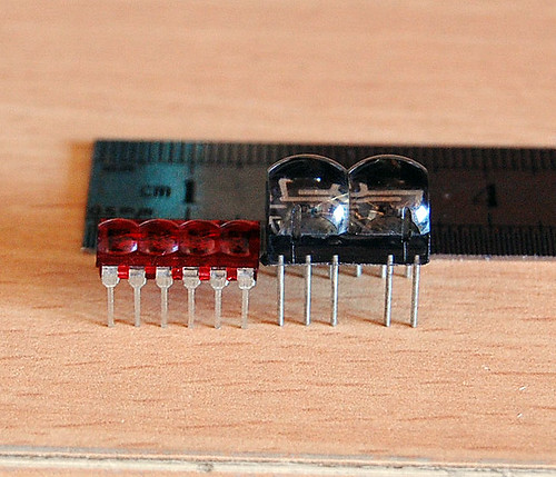
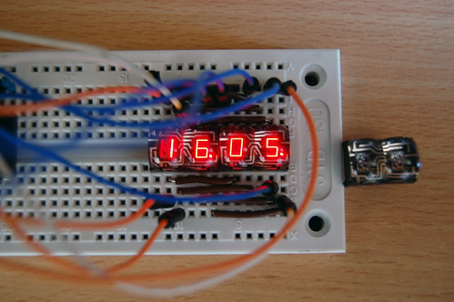
We used the excellent New Micros FORTH boards in the Microship project, and find ourselves with a few parts left over. This is part of the 2x4 series of stackable boards, which are very easy to use. There is a PDF data sheet here, and from the NMI website, here are the details of this board:

The NMIS-9003 Real Time Clock Board, in 2x4"s[tm] card format, provides a JEDSTACK[tm] computer system with processor-independent date and time information.

FEATURES:

  • Built-in Time (hour, minute, second) and Date (year, month, week, day) counters
  • 12hr/24hr clock switchover function and automatic leap year setting
  • Interrupt masking
  • 30 second error-adjustment function
  • CMOS design includes low current consumption and backup function

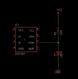
The NMIS-9003 features a built-in quartz oscillator, time and date function, and CMOS circuitry for low power consumption. The EPSON 62421A Real Time Clock chip is the key part on the board. The 62421A's registers are memory mapped by the card. Its registers provide the second, minute, hour, day, month, year, day of week and control information to the processors. The 62421A can operate in either 12 or 24 hour mode. Leap year timing is automatic.

The real time information is maintained and updated through processor power down periods by the on-board, 3V lithium coin battery. Two battery sockets are installed on the board, allowing a fresh battery to be inserted in the open socket before the removal of a failing battery.

The NMIS-9003 can also provide real time interrupts to the processor. This can be useful when very low power modes are desired, in which the processor wakes up only occasionally. The NMIS-9003 can create such an interrupt once an hour, once a minute, once a second, or 64 times a second.

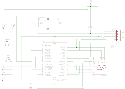
A Vertical Stacking Connector in the lower right hand corner (top view) provides connections to the processor's address and data bus, control signals, 5V power and ground. Address decoding of the Real Time Clock chip's space in memory is accomplished by two octal comparators and 16 two-position jumpers. The NMIS-9003 occupies 16 addresses. Any 16-byte boundary in the 64K address space of the JEDSTACK[tm] processor's bus can be selected by correct jumper placement.


Olimex MT-128 Development Board for AVR ATMega128, with JTAG


This beautiful little board for ATMega128 development was made by Olimex, and provides lots of I/O to help get your project running quickly. There are detailed specs at this Olimex page, including links to PDF manuals, demo code, schematics, and a complete open-source weather station. We only have one of these for sale; our new research vessel has standardized on the Arduino platform, so this is no longer needed. It has been tested with the supplied demo code, but never been fully in use.

FEATURES:

  • MCU: ATMega128-16AI with128K Bytes Program Flash, 4K Bytes data EEPROM, 4K Bytes RAM
  • JTAG connector for in-circuit programming and debugging with AVR-JTAG
  • ICSP 5x2 (10) pin STKxxx compatible connector for in-circuit programming with AVR-PG1B or AVR-PG2B
  • RS232 connector with TTL levels
  • RS232 interface circuit with Tx, Rx signals
  • RS232 DB9 female connector
  • Dallas touch button port
  • Frequency input
  • LCD 16x2 display
  • LED status
  • five buttons
  • Buzzer
  • power supply circuit +5V, 78L05 with plug-in power jack and diode bridge
  • 32 768 Hz oscillator crystal
  • 16 Mhz crystall oscillator
  • power supply filtering capacitor
  • RESET supervisor IC ZM33064
  • RELAY with 10A/250VAC NO and NC contacts with screw terminals
  • extension headers for unused in the schematic ports available for external connection
  • PCB: FR-4, 1.5 mm (0,062"), green soldermask, white silkscreen component print
  • four mounting holes 3.3 mm (0.13")
  • Dimensions: 120x38 mm (4.7x1.5")

Tuesday, November 10, 2009

New Micros NMIS-9002 3-channel, 16-bit counter


This board, part of the New Micros 2x4" series, is based on a high-performance programmable counter for system timing control. Three 16-bit counters, each with its own clock input, and OUT pin, can be clocked from D C to 8 Mhz. Under software control, the uPD71054 can generate accurate time delays.

The chip contains three counters capable of binary, or BCD, operation. There are six programmable count modes. The counters operate independently and each can be set to a different mode.

After initialization, the uPD71054 can count the delay and generate an interrupt when the task is complete, without further CPU intervention. This eliminates the need for software timing loops and frees the CPU for other tasks.

As with all the boards in this series, a Vertical Stacking Connector in the lower right hand corner provides connections to the processor’s address and data bus, control signals, 5V power and ground. Address decoding of the drivers’ space in memory is accomplished by two octal comparators and 16 two-position jumpers. Each jumper setting corresponds to the state of a particular address line. The NMIS-9002 occupies 4 address locations. Any 4-byte boundary in the 64K address space of the JEDSTACK processor’s bus can be selected by the correct jumper placement.

I used this series quite successfully during the Microship project, and this is excess inventory... only one is available.

Microchip dsPICDEM 28-Pin Demo Board with dsPIC30F2010


This unused development board is based on the Microchip dsPIC30F2010, a 16-bit,30 MIPS RISC machine optimized for motor control. This is in current production and there is a detailed dsPIC30F2010 product page that includes links to PDF data sheets and application notes.

This Starter Development Board has a socketed dsPIC30F2010 digital signal controller, power supply regulator, crystal oscillator, ICD header, serial port, power on indicator, Reset push-button, 28L SOIC layout pad and a prototyping area. It operates from a 9-volt supply, includes a power-on program that demonstrates interrupts, device I/O, and UART communications. There is a PDF Users Guide for the board here.

This is new, and arrived here with a project in mind... but we are not going to need it. Looks like a pretty capable chip, though, so if you have some serious motor control apps this is a way to get to know the device without having to cobble together a breadboard.

Arduino Duemilanove Microcontroller - ATmega168


We have fallen in love with these things here at Nomadic Research Labs, and are using 15 of them on the research vessel Nomadness to take care of all embedded control and data collection (see this blog post for overview and drawings). The Arduino boards are cheap, low-power, and exceedingly easy to use: just plug them into your Mac/Linux/Windows machine with a USB cable, run the development tools freely downloadable over here, and start playing. The language is a rich dialect of C, with such niceties as direct pin number references and painless support for I/O and serial communications, along with a very quick development cycle. The community is highly supportive... have a browse around the resources and forums at the Arduino site and you'll likely be drawn in. Since discovering these, I have abandoned all the other development boards that have accumulated here in the lab.

The Arduino Duemilanove (Italian for "2009") offered here is a microcontroller board based on the ATmega168 (PDF datasheet). It has 14 digital input/output pins (of which 6 can be used as PWM outputs), 6 analog inputs, a 16 MHz crystal oscillator, a USB connection, a power jack, an ICSP header, and a reset button. It contains everything needed to support the microcontroller; simply connect it to a computer with a USB cable or power it with a AC-to-DC adapter or battery to get started.

There are lots of shields available which plug directly into the board and provide workspace or specialized functionality (including ethernet, XBee wireless, displays, motor control, and general prototyping). We'll be adding to our inventory of these and related items as the product line develops.

Sunday, November 8, 2009

Programming Adapter with ZIF Sockets

Introduction:

This programming Board is designed to be used with Serial, ICP and USB programmers detailed elsewhere on this site.

PB2 board is similar to PB1 but contains ZIF sockets with 20Pin, 18Pin & 40Pin. (18pin socket may be substituted by 20pin ZIF in Kits, as 18pin ZIF are unavailable at times)

20Pin socket is used for programming of 8pin, 14pin & 20pin PIC Micro Controllers.

18pin ZIF is dedicated to 18pin PICs.

40pin ZIF covers 28 and 40pin PIC Micros.

PB2 kits are now available with one 20/18 PIN ZIF, One 40PIN ZIF or 2x20 & 1x40PIN ZIFs. In addition to this, you may also order PB2 with Standard IC Sockets.

Basic Kit contain LVP pull-down switches for those trying to program PICs with LVP, 4 0.1uf ceramic capacitors, a 10K LVP resistor and 6 PIN R/A Male header.

Serial , ICP and FD-UPP Programmers:

This board is 100% compatible with FD-ICP, FD-SPP and FD-UPP Programmers

Interface to PICKIT2:

This board is pin compatible with PICKIT2 & FD-UPP programmers. You may use this programming board to program 8, 12, 18, 20, 28 & 40 pin PIC Micro Controllers.


Picture of the Programming Adaptor Board: PB2


Programming Adaptor Board for FD-SPP/ICP/UPP

Introduction:

This programming Board is designed to be used with Serial, ICP and USB programmers detailed elsewhere on this site.

In view to keep cost low, board contains simple DIP sockets of 20Pin, 18Pin, 28Pin & 40Pin.

20Pin socket may be used for programming of 8pin, 14pin & 20pin PIC Micro Controllers.

18, 28 and 40pin sockets are specific to such PICs.

New PB1.2: Revised PCBs : 12th Dec 07


In my new run of PCBs, I have 20, 18, 28 and 40pin DIP sockets. I have also amended 0.1uf Tantalum capacitors by 0.1uf ceramic.

I have added LVP selector, a 4 position slide switch, for those working with Low Voltage Programming, where a pull-down is required. LVP pull-down resistor may be selected by user on Specific Chip socket for specific purpose.

Interface to ART2003 Programmer:

In view to extend various PICs, hhis programming board may be used with FD-ART2003 Parallel Port Programmer detailed elsewhere. However, you will have to do external wiring between two boards yourself.

Serial & ICP Programmers:

This board is 100% compatible with FD-ICP and FD-SPP Programmers

Interface to PICKIT2:

This board is pin compatible with PICKIT2 & PICKIT2 USB programmers. You may use this programming board to program 8, 12, 18, 20, 28 & 40 pin PIC Micro Controllers.

Picture of the Programming Adaptor Board: PB1.2


Parallel Port Programmer for PIC 18Fxxx

FD-ART2003

Developed specifically for programming of PIC 18F2550 micro controllers, this parallel port, no-power, programmer is the smallest of all programmers ever built.

A DB25 Male Connector, one capacitor and a resistor makes this Port Powered programmer.

Programmer takes its power from Parallel Port pins 2-9. VPP for this programmer is 5V and hence "LVP" must be selected in programming software. (See art2003 screen shot Document given below)

I built this programmer to write firmware (boot loader) into my PIC18F2550 which I wanted for my PICKIT2 inspired USB programmer.

A free windows based program called WINPIC800 V.3.59 is available for free download. This software is not intended for this programmer alone, you may use it for many other programmers including few detailed here on this website.

Although, programmer socket is wired for PIC18F250 & 2550, other PICs with similar pin connections may be programmed. You may also wire your own socket for different type of PIC if the same is supported in the WINPIC800 (under Art2003 selection).

And there is always a possibility to use Programming Adaptor board wired to this programmer to get larger acceptance of various PICs.

This programmer is designed on a 6cm X 4cm Doubled Sided PTH Board.

Picture of the PIC 18Fxxx Parallel Port PIC Programmer


Parallel Port ICP PIC Programmer - FD-ICP

Introduction: FD-ICP

In addition to Simple Parallel port PIC Programmer detailed elsewhere on this site, I wanted a Parallel port PIC Programmer with ICP output socket. This project came to my mind from a concept by OziPic’er.

This programmer is built for Free Windows Software called WinPicProg developed by Nigel Goodwin and uses a 74HC14 instead of 74LS05 used on other parallel port programmers.

Programmer PCB is double sided PTH board, 6CM X 8CM and has a 6 Pin Female ICP output connector with pin connections exactly same as PICKIT2 of Microchip.

An adaptor suitable for 8, 14, 18, 20, 28 & 40 Pin PIC Micro Controllers is available to use with this ICP Programmer.

It should be noted that even though, all kind of PIC Micro Controllers may be accepted by Adaptor board, only those supported by software might be programmed.

Hardware:

You require a 12-18V AC or 14-18VDC power supply. When connected, an LED labeled, as “Power” will light. Indicates that 13.2V is now available on board. This is Vpp supply used for programming.

Run WINPICProg software on your PC to check out if rest of the hardware is functioning well. Vdd LED will light when Vdd (Target Power) check box is ticked on software window. Similarly, Vpp lights may be tested by selecting appropriate devices.

Although, Vpp & Vpp2 are generated separately by software, they are combined within the hardware to produce a single Vpp for ICP connector. Q6 is used for Vpp reset.

Compatibility with OS:

This is a Parallel Port PIC programmer and is duly tested on Win98. If you decide to make or buy this programmer and want it to use with XP/Vista etc, please ensure that you understand your OS very well. I wont be in a position to support for questions related to Port configuration etc for specific OS. For XP/Vista etc please look for a suitable USB PIC Programmer.

Picture of the Parallel Port ICP PIC Programmer

PIC ICP PROGRAMMER BY FOX DELTA


Adaptor Board:

This board is required if you wish to program PIC Micro Processors not fitted in circuit boards already.

On this board we have different sockets to accommodate various types of PICs.

Picture of the Programming Adaptor Board


Serial Port PIC Programmer for PIC16 & PIC18

Model: FD-SPP

PIC Programmer is an essential tool if you wish to learn or build projects with Microchip PIC Micro Processors.

This programmer is for those who do not have a Parallel Port on their PC. Programmer may be used with Free Windows Software such as "PIC PROGRAMMER Professional Serial" from Oshosoft and may work well with other serial programming software.

Programmer PCB is double sided PTH board measuring 6cm X 8cm. Since my idea was to make this programmer small in size with ICP capability with ICP header having PICKIT2 compatible pin connections, I have used a separate Programming Board containing IC sockets for 20 (Includes 8,14 & 20 pin PICs), 18, 28 & 40 pin PICs.

Firmware in PIC 16F628A controls TXD, RXD, Vdd & Vpp lines to program the Target Chip. A true RS232 interface IC is used to connect programmer to PC's com port.

To use this Programmer, you will require a 14-20V DC or AC Power adaptor, A Programming Adaptor Board and a serial cable. Programming Adaptor Board is included with this programmer.

If you wish to build this programmer using your own parts, you may buy a PCB for this project.

PCB with Pre-programmed firmware in PIC 16F628A is also available for those who do not have a programmer.

If wish to build this programmer using PIC16F628A, 627, 627A or 628, you may request for a suitable firmware with 8, 10, 12, 16 or 20MHZ crystal frequency.

Free firmware for PIC16F628 & 628A is already supplied here for crystal frequencies of 8, 10, 12, 16 & 20MHZ.

Free Serial Port Prof Programming Software is suitable for programming, both PIC16F & PIC18F chips, using this programmer.


Picture of the Serial Port PIC Programmer

Fox Delta Professional PIC Programmer FD-SPP


Picture of the Complete Programmer assembled

FD-SPP with PB1

Parallel Port Microchip PIC Micro Controller Programmer

PIC Programmer is an essential tool if you wish to learn or build projects with Microchip PIC Micro Processors.

This programmer is built using Free Windows Software called WinPicProg and other similar software from PICALLW or Oshosoft

Programmer PCB is double sided PTH board. In this programmer, you have a 0.3 Inch IC socket (40pin) on the main board, where you can place either 8, 18 or 28pin ICS for programming. An adaptor PCB with male/Female header is supplied with this kit for 40pin DIP. (without 40pin DIL Socket)

However, make sure that you insert PIC ICs at the proper location on this 40Pin socket. Suitable markings of placement are made on the PCB.

I have included required hardware settings in the DOC for Oshonsoft parallel programming software

Warning: This programmer is controlled from Parallel Printer Port of your PC.
If you keep Micro-controller chip on this powered programmer & try to PRINT from any application, it would damage the micro-controller. Apply power to this programmer only after running the programming software.

Picture of the PIC Programmer KIT with Standard Socket:


To use this programmer, all you require is 12-18V AC Adaptor and a cable to connect to the parallel port of your computer.

PICKIT2 Compatible USB PIC Programmer

Introduction: FD-UPP

PIC Programmer is an essential tool if you wish to learn or build a project that uses Microchip PIC Micro Processors such as DDS, Repeater Controllers and LCD Power Meter.

This programmer is built around Microchip’s PICKIT2 programmer, which is basically a surface mount, fully assembled, ready to use product. It’s called a “Kit” but it is not!! This one is a true kit for radio amateurs.

Benefit of making PICKIT based programmer for amateur radio is further supported by freely downloadable PICKIT2 software for windows. Microchip keeps this software updated for new devices that they launch.

In this project, to make it simple, I have removed the voltage level change capability of firmware for VDD 3V. Means, this programmer will only program 5V PIC Micros.

Project uses a PIC16F2550 in 28pin DIP package. All diodes are standard lead type & FETs are either in TO92 or HEXDIP packages, to make assembly smooth & easy.

Kit is supplied with FD-PB1 Programming board. PB1 uses standard IC Sockets for 40, 28, 8,14, 20 & 18PIN DIP PIC Micros.

In view to make a suitable metal case for this programmer, FD-UPP has two headers H1 & H2, which will be used by “piggy back” Programming board I will design later.


Adaptor Board:

FD-UPP KIT includes PB1, a simple programming adepter board.
On this board we have different sockets to accommodate various types of PICs. It accepts 8, 14, 18, 20, 28 and 40 PIN DIP PIC Micro Controllers.


Monday, November 2, 2009

How to program Microchip PIC microcontrollers

This is something I learned to do fairly recently (6 months ago) on my Mac, after looking for the correct tools for a long time (like a whole year before that). Granted, I have been able to program PICs with my PC for 2 years through the "official" methods, and with a little help from the existing virtualization options.

But today I want to describe how to do it in the Macintosh, 100% no emulation, no virtualization.

First, you will need is a Pickit-1 like mine. They are dirt cheap these days, like $36 direct from Microchip.

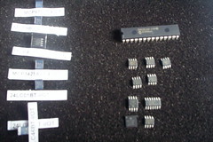
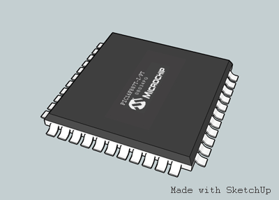
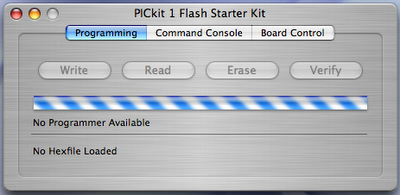
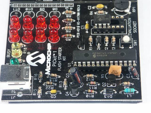
After ordering the Pickit, you can get free samples from the company's website. Be sure to check the PIC compatibity within the Pickit-1. I ordered a bunch of 16F675 because they are the only supported PICs with hardware UARTs in them.

Second, obtain a copy of Microchip OSX Pickit tool. It comes with no official support, but it is open source. Get a copy here: Intel, PPC. Use the OSX tool to test that you can download the .HEX files included in the CDROM.


Congratulations. Now you can program PIC microcontrollers!

Of course, you will need a compiled/assembled HEX file to flash your PIC now. There are many, many ways of achieving this, and the ways are more numerous with VPC/Parallels/Bootcamp, but I am working on another blog post that will describe how to code the PIC within OS X.