Sunday, October 25, 2009

Microchip Technology Sets New Industry Standard

Microchip Technology Inc. announced full MPLAB® development tool availability to support today’s launch of the new PIC32 32-bit microcontroller family. The immediate availability of a broad and compatible suite of tools means that Microchip’s current customers can easily make the transition from 8- and 16-bit microcontroller development to 32-bit development. At the same time, designers new to Microchip will find a highly integrated 32-bit toolchain that sets a new industry standard for integration and ease of use. PIC32 tool support is available today from the free MPLAB IDE version 8.0, the MPLAB C32 C compiler (including a free evaluation version), the MPLAB REAL ICE™ emulation system and the MPLAB ICD 2 in-circuit debugger.

microchip.gif


With 16 years of experience in the marketplace and full support for all PIC® microcontroller families, the MPLAB IDE is the tool of choice for the majority of Microchip’s customers. The free MPLAB IDE supports the PIC32 family’s advanced debugging features, such as hardware-based complex break points, trace debugging, as well as full project-management features for developing complex projects.

micrrochipchart.gif


The MPLAB C32 C compiler (part # SW006015) is available now with a free Student Edition that supports 64 KB of compiled code, and a full edition that supports unlimited compiled code. The MPLAB C32 is fully integrated with the MPLAB IDE and select third-party IDEs. The compiler package includes an ANSI C compiler, assembler, linker and peripheral libraries for the PIC32 family. The peripheral libraries are API compatible with the MPLAB C30 C compiler that is used with Microchip’s 16-bit MCU and DSC families. The end result is highly optimized code for smaller, faster-running applications that are portable across Microchip’s 16- and 32-bit portfolios.

PIC32-Starter-Kit-Photo.gif

Microchip Switches to MIPS Core for PIC32

Last month, Microchip announced a new 32-bit microcontroller chip family, the PIC32. With this family, Microchip—a long-time player in 8- and 16-bit microcontrollers—is going after the 32-bit microcontroller market, and making a big change in architecture. Unlike Microchip’s earlier chips, which were based on the company’s proprietary processor architecture, the new family is based on the MIPS M4K core. PIC32 chips, which are currently sampling, will operate at up to 72 MHz, with pricing ranging from $2.95 to $5.30 in 10K quantities. A block diagram of the PIC32 is shown in Figure 1.

MIPS PIC32 Block Diagram.jpg

With the success of its previous products, it’s somewhat surprising that Microchip has switched horses now—but there are good reasons for doing so. It’s expensive to develop and maintain an in-house processor architecture, and it can be challenging to provide the full ecosystem—sophisticated tools, operating systems, reference designs, software libraries, etc.—that customers have come to expect. By going with a MIPS core, Microchip can leverage MIPS’ substantial resources and third-party support, while using its own existing peripheral libraries to create chips that are pin- and peripheral-compatible with earlier Microchip products (more on this later).

Of course, Microchip could have achieved the same effect by going with an ARM core (the relatively new Cortex-M3 springs to mind), which is what several of its competitors have done. According to Microchip, the company chose the M4K because it provided the best fit for deeply embedded applications—the best combination of power, performance, interrupt capabilities, code density, and potential future customizations. The M4K provides a co-processor interface, and also allows licensees like Microchip to define custom instructions. If Microchip decides to use custom instructions, however, they may compromise their ability to leverage some of the existing development infrastructure.

BDTI recently completed an evaluation of the MIPS M4K core, with a focus on assessing its signal processing features and capabilities. The M4K is not a DSP processor, but microcontrollers are increasingly called upon to do simple signal processing, so it’s useful to understand its capabilities in this area, and compare them to those of the Cortex-M3. Here are a few of the highlights of our evaluation.

The M4K core has more registers than the Cortex-M3 (32 vs. 16), and Microchip went one step further by configuring the core with an additional 32 shadow registers. More registers can mean more efficient software; they can be used, for example, to store more coefficients, parameters, and data values on-core, allowing instruction slots that would otherwise be needed for memory transfer operations to be used to increase the throughput of computation operations. But the Cortex-M3 has an advantage in multiplications—it can do single-cycle 32x32 multiplication, which the M4K cannot (it requires at least 2 cycles). The M4K can, however, do single-cycle 32x16-bit and 16x16-bit multiplies.

Compared to Microchip’s 16-bit, DSP-oriented dsPIC family, the PIC32 may be somewhat faster on typical DSP code. The newer chip can perform the same number of 16x16-bit multiplications per cycle (one) and executes at roughly twice the clock speed of current dsPIC chips. However, the dsPIC includes DSP-oriented features that the M4K lacks, such as support for saturation and rounding, hardware looping, and specialized address modes. Cumulatively, these features can have a significant impact on DSP performance—both in terms of speed and energy efficiency. It will be interesting to see whether Microchip ends up licensing a higher-performance MIPS core (such as the DSP-oriented 24KE) for future DSP-oriented chip families, or adding its own DSP-oriented custom instructions, as it did with the dsPIC.

In its press release, Microchip characterizes the PIC32 as being “software compatible” with its earlier chip families, but this characterization is slightly misleading. The chips are software compatible if you’re working in C (which Microchip expects most of its customers to do) but because the new chip family is based on a different instruction set architecture, any legacy assembly code will need to be rewritten.

The “software compatibility” Microchip is talking about is more of a system-level compatibility. Because the new chips use the same peripherals as the older chips, any C code written to use specific peripherals will work on the new chips, and Microchip provides peripheral libraries with compatible APIs. In addition, the new family is supported by the same tool chain (MPLAB) as all the other Microchip MCUs. In fact, according to Microchip, tool chain compatibility was another reason they chose the M4K; MIPS had placed the M4K compiler in the GNU compiler base, and Microchip was already using GCC for its 16-bit MCUS—thus making for an easier integration with Microchip’s existing tool chain.

Microchip’s decision to move to a licensable core—and to the M4K in particular—appears to be a reasonable one. Time will tell if Microchip’s customers will make the jump with them.

PCM2706 High Fidelity USB Soundcard or USB Headphones

This is a high fidelity external USB Soundcard / USB Headphones project that can be built for your PC or Mac. It is based on the latest PCM2706 IC which functions as a high quality, crystal clear 16-BIT Stereo DAC. It is a single chip digital-to-analog converter that offers two D/A output stereo channels, digital S/PDIF output and requires very few external components. PCM2706 includes integrated USB 1.0 & USB 2.0 compliant interface controller and it is conveniently powered directly from USB connection. PCM2706 is a USB plug-and-play device and does not require any driver installation under Windows XP and Mac OSX

Friday, October 23, 2009

dsPIC 33F128MC706 NUE-PSK Digital Modem

dsPIC NUE-PSK Digital Modem

PSK31 is one of the latest communications modes to capture the interest of hams worldwide. Its inherent ability to dig out low, near-inaudible signals is ideally suited for low power QRP enthusiasts. The PSK31 digital modem engine, however, requires intense DSP processing that is only commonly available in PC sound card. Thus the PSK operator desiring portability for field operation is locked into using a laptop computer as a controller, which results in a cumbersome station.

This project shows you design and construction of a standalone, battery-operated digital modem using a Microchip dsPIC microcontroller. The project includes a character display for transmit and receive text data, and a graphic display showing band spectrum and tuning indicator. Using GPL open source software, the modem can be homebrewed for less than $50 parts cost. When coupled with an SSB-capable transceiver or with a popular PSK-xx transceiver board from Small Wonder Labs, you too can have an effective portable PSK31 station.

© George Heron and Milton Cram

Download
Project documentation


tag : Digital Modem, PSK, DSP, MCU dsPIC33F128MC706, Communication


Tuesday, October 13, 2009

LED Operates Directly From AC


Acriche is the world’s first semiconductor light source that operates directly from AC power without a converter. This makes it suitable for many residential and commercial lighting applications where the main source of available power is AC.

  • Operates on AC power without additional conversion circuitry
  • Operating Voltage: 100V, 110V, 220V, 230V
  • Long Life: over 35,000 hours
  • No converter loss = higher fixture efficacy
  • Operating frequency: 50/60 Hz
  • Available in warm white and pure white
  • Multiple package options
  • See Link

    Monday, October 12, 2009

    PIC Wireless Networks Wifi (Hotspot) Detector

    PIC Hotspot detector
    This wireless detector project allows you to sense the presence and relative signal strength of wireless hotspots. It is "always on" and communicates the presence and signal strength of an in-range hotspot by way of sequences of pulses - like a heartbeat you can feel. The stronger and faster the "heartbeat", the stronger the wireless signal detected.

    This project consists of a microcontroller PIC 12F629, some custom interface electronics, a small vibe motor, and an off-the-shelf Wi-Fi detector from D-Link. The microcontroller periodically "presses" the button on the detector to initiate a reading. The microcontroller "reads" the output from the detector indicator LEDs and uses this as the basis for pulsing out a signal on the vibe motor, which the wearer can feel.

    tag : wireless networks, hotspot detector, Wi-Fi strength signal indicator src

    Friday, October 9, 2009

    Microplex (MPX) Project

    This project will allow you to build an interface from your PC to Microplex dimmer boxes. The Microplex (MPX) project is a collection of the interface and supporting software. The primary purpose was to link lighting control to sound and music. It is recommended that you have a Microplex based lighting control system or knowledge of it before reading the following articles.

    Microplex Protocol Specification (As best we know)

    mpx protocol diagram 
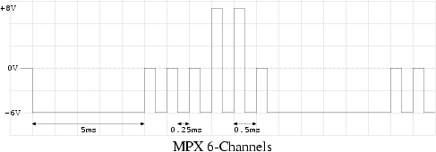
The Microplex protocol is a proprietary analog multiplexing lighting control protocol used primarily by NSI (Leviton). It is sent across standard XLR (Microphone) cable. Three wires are used which are +12v, GND and Signal. From our examination the Microplex protocol can handle up to 100 channels. However, the more channels, the slower the refresh rate.

    The Microplex signal line swings from +8v to -6v. This was learned by examining the signal on a scope. The actual specification could be different. +8v is Fully ON and 0v is Fully OFF. Negative voltage, -6v, is a sync pulse.

    The protocol starts off by sending a 5ms sync pulse. This sync pulse resets the channel counter in the dimmer boxes to zero. After the pulse, the level for the first light is send for 0.25ms. If the light is to be off, then the level will be zero volts. Next a 0.25ms sync pulse is sent. This increments the channel counters on the dimmer boxes. The 0.25ms pulses are repeated until all the channels have been sent. The process begins again with the 5ms sync pulse.

    The frame time (time from one 5ms sync pulse to the next) can be calculated with the formula t = 5ms + (2x * 0.25ms) where x is the number of channels and t is in milliseconds.

    DTMF decoder 2 Circuit


    The DTMF decoder 2 is a useful tool used for decoding DTMF (Dual Tone Multi frequency) generated by telephones. The decoded digits are viewed on a 16x2 LCD screen. The DTMF decoder can be directly connected to a Serial port to view the digits in HyperTerminal on a computer. The decoder stores the last 234 received digits in EEPROM. The contents of EEPROM can be viewed on the LCD screen via two scroll buttons. Total power consumption is 12mA. The DTMF decoder has two inputs. A RJ11 jack for connecting to the phone line and a 1/8" audio jack for connecting to a scanner, tape recorder or other audio output device.

    The list includes parts for the DTMF Decoder. All part numbers are for Digikey unless their is a link to another supplier.

    Quantity Value Description Digikey Part No. Component
    1 78L05 +5V Regulator 296-1365-1-ND U1
    1 MCP120 Supply Supervisor MCP120-450DI/TO-ND U5
    1 AT90S2313 Microprocessor AT90S2313-10PI-ND U2
    or
    Alternative Micro ATTINY2313-20PI-ND U2
    1 MT8870DE DTMF Decoder E-SONIC U4
    1 4N25 Opto-isolator 160-1300-5-ND U3

    1 10uF Dielectric P10316-ND C1
    4 4.7 uF
    P1199-ND C6,7,9,10
    3 0.1 uF
    P4525-ND C2,4,8
    2 18pF
    P4840-ND C11,C12

    1 4.7K 1/4 Watt 4.7KQBK-ND R4
    3 10K 1/4 Watt 10KQBK-ND R1,2,6
    2 47K 1/4 Watt 47KQBK-ND R7,R8
    1 390K 1/4 Watt 390KQBK-ND R9
    1 20K POT Vertical POT 36G24-ND R5

    1 16x2 LCD 73-1025-N LCD
    1
    RJ 11 Jack CCM9000-ND Phone
    1
    1/8 Audio Jack CP-3543N-ND Audio
    1
    9V Connector BS6I-HD-ND Batt
    1
    20-pin Socket A9420-ND
    2
    Push Buttons P8006S-ND S1,S2
    2 0.1" 7-pin Header strip WM4005-ND
    1 3.579545 Mhz 3.58 Mhz Crystal 300-6001-ND Y1
    1 Female DB9 Connector A2047-ND DB9

    Windmeter / Anemometer Circuit


    The circuit for the Windmeter is self powered. A 12v solar cell array provides power to the circuit and charges the battery during the day. At night the 12v battery is used to power the circuit. Operation for many days without sunlight is required, so the circuit operates at 3.3v and uses a high efficiency switching power supply. The circuit draws 1.35 mA at 12v. The circuit should operate for over 50 days without sunlight from a fully charged battery. The solar cell will take 3 days to fully charge a dead battery. The circuit should never loose power.

    Power enters the circuit through L7 and D1 to prevent reverse battery connection. C10 is used as a input filtering capacitor while C11 is used as a input de-coupling capacitor. U3, L1, D2, and C12 form the switching power supply. R3, R6 and R7 form the low battery power down.

    A magnet and Hall effect sensor are used to measure RPM of the rotating cups. One pulse per revolution is produced. The sensor is on the back of the PCB and the magnet is attached to the rotating shaft. Microcontroller U2 is used to calculate wind speed from the pulses produced by the Hall sensor. The micro also records the varying speeds and provides a interface to a Laptop / computer. U1, a low power RS232 1 channel driver, is used to join the PC serial port and the micro's UART. C2 - C5 are used by the RS232 Driver IC to form charge pumps. C1, C6, C7, C13 are used as bypass / de-coupling capacitors throughout the circuit. C8, C9 are used to help start oscillation. The crystal of 4.096 Mhz was selected for easy and accurate time measurement. R1, R2 are used to form a voltage divider which feeds ADC channel 0 to measure Supply voltage. Q1 and Q2 control the power applied to R1 and R2 to improve power consumption.

    Tuesday, October 6, 2009

    IC4013 Combination Lock Circuit

    Combination Lock circuit

    Combination Lock circuit

    This circuit is very basic to build. To open a the lock which is connected to the K1 Load. you must press each momentary switch in the correct sequence. The sequence used in this circuit is S1,S2,S3,S4. If any of the other switchs are pressed the circuit will reset and you will need to start over. Depending on how you wire the switchs, you can use any 4 switch combination

    Wireless Auto Tachometer Circuit

    To use the Tach, turn it on and let it sit for one minute to allow for temperature stabilization. Extend the antenna, select the right number of cylinders and hold the unit over the engine. If the reading is erratic or the needle jumps around, move the antenna closer to the ignition coil or spark plug wires.
    Wireless Auto Tachometer Circuit

    Wireless Auto Tachometer Circuit

    Using the Tach circuit, turn it on and let it sit for one minute to allow for temperature stabilization. Extend the antenna, select the right number of cylinders and hold the unit over the engine. If the reading is erratic or the needle jumps around, move the antenna closer to the ignition coil or spark plug wires.
    Wireless Auto Tachometer PCB
    Wireless Auto Tachometer PCB

    Accessory List.

    • C1 1 0.47uF Capacitor
    • C2 47uF Electrolytic Capacitor
    • D1 8V 1W Zener Diode
    • D2, D3, D4 1N914 Diode
    • M1 200uA Meter
    • Q1, Q2 2N3391A Transistor
    • R1, R2, R9 1K 1/2 W Resistor
    • R3 47K 1/2 W Resistor
    • R4 10K 1/2 W Resistor
    • R5, R6 25K Trim Pot
    • R7 10K Trim Pot
    • R8 200 Ohm 2 W Resistor
    • R1 15K 1/2 W Resistor
    • R1 2.2K 1/2 W Resistor
    • S1 SPST Togglae Switch
    • S2 Three Position Single Pole Rotary Switch

    Remark:
    1. Unit Calibration as folows:

    1.1.Install the circuit:

    1.2. Turn on the Tach and allow a few minutes for temperature stabilization.

    1.3. Set S2 to 4 cylinders and adjust R5 for a meter indication of 180 (1800 rpm).

    1.4. Set S2 to 6 cylinders and adjust R6 for a meter indication of 120 (1200 rpm).

    1.5. Set S2 to 8 cylinders and adjust R7 for a meter indication of 90 (900 rpm).

    2. Used the Tach, turn it on and let it sit for one minute to allow for temperature stabilization. Extend the antenna, select the right number of cylinders and hold the unit over the engine. If the reading is erratic or the needle jumps around, move the antenna closer to the ignition coil or spark plug wires.

    3. This unit draws power from a car battery. If it is connected backwards, it will not work, but it won’t be damaged.

    LCD Thermometer Sensor Circuit

    saw many car product in thermo sensor ,so i would like to show you the LCD thermo sensor which can modify for your car.


    LCD car thermo circuit

    LCD car thermo circuit

    When the thermometer is the IC thermo sensor (S8100) or diode (1S1588) is used as thermal sensors.

    When using the IC thermo sensor, the thermometry to +100 ° C -40 ° C are possible.
    Also, when using the diode, measured at 150 ° C from -20 ° C are possible. Both sensors are contained in the set.
    This time I used the diode as a heat sensor to measure more than 100 ° C. ICL 7136 of Intersil (Harris) used for the thermometer and measure the voltage change minute by management before the temperature diodes.

    The 3-1/2 digit LCD (SP521PR) applied to the screen. The most significant digit can display a “1″.
    ICL7136 electricity consumption is very small and it is possible to run about 3 months with 9-V cell.

    The essential parts are contained in the set. The plastic casing and the cell is contained. But there is a cable connecting the sensor.

    Car Water Temperature Sensor With Display

    Engine water temperature sensor circuit

    Engine water temperature sensor circuit

    For user who love developping in electronic project ,we have some circuit for Car Boiler or water Temperature Sensor of this circuit can be to display Temperature of Car water Boiler with 7-Segment Main of circuit .car_temp

    We have use IC CA3161 and CA3162 for control all,The Car Water Temperature Value can’t be keep always while no power supply as It hasn’t EEPROM to save.
    This circiut will be display for you monitoring only that is make sense to implement in your car.

    This circuit measures the car water temperature.
    The IC CA3161 is a counter and 7segment LED driver to display amount of temperature on 7segments.
    About a temperature sensor is a diode which number 1N4148.
    This is like of the Car Radiator.
    Connect to the 5 Vdc power supply from Car Battery that you can use a LM7805 for +5Vdc regulation with low cost voltage regulator.

    For the method of temperature measurement: first after application of at least 2 currents of a thermal sensor, including at least two output signals are generated calculating an analog signal to the temperature of the reaction at least two signals, the analog signal representative of temperature to the temperature sensors, a calibration, the calibration factor is calculated by applying the order of leastthree thermal sensor, and calibration of a gap in the temperature of the concept of analog signal, that the development gap-term is at least a series of parasite resistance to the thermal temperature sensor and the signal processing theanalog digital signal to a temperature reference value for the conversion of the reference value for the transition is consistent with the calibration.

    BC108 Water Activated Relay Circuit

    Water Activated Relay circuit

    Water Activated Relay circuit

    For electronic circuit has two transistors wired as a pair, together with high gain.

    2N2222A transistor T1 and T2 is BC108.
    The actual profit will be the proceeds of any beta-transistors with a minimum of 140 x 110 or 15,400.
    Power supply is a voltage from 4.5 to 15 volts, a kind of relay 5 Volt at 60 mA is required to in this case, any liquid with a stream of at least 4 others to the relay. It is easy to reach with tap water or rain.

    IC 4027 Low Cost Stepper Motor Circuit

    I had immediately into my document. I do not know where it came from, but it seems that I photocopy a few years.

    I think it should be very helpful, so I decided it here. The circuit is very simple and inexpensive. It is a good thing, since most lines step motor controllers are very expensive. The circuit is made of standard components and can easily be adjusted by a computer. If you cheap surplus transistors and stepper motor, the price of the circuit can be less than $ 15.

    This stepper controller circuit shown here can used to control the unipolar stepper motor,which has 4 coils . The stepper controller circuit can drive for a motor current of up to about 500 mAmp/Winding by suitable heat sinks for the SL-100.

    directsinks


    In higher currents power transistors seem 2N3055 can be used as darlington pair along with SL-100. All diodes are used to protect back current the transistor from transients.

    *** Remark ***

    • You may be able to substitute any standard (2N3055) power transistor for Q1-Q4 or
    • get IC type UL to modify for transistor.

    • Every time in move the motor put signal the STEP line is pulsed, the motor moves one step.
    • Switch S1 for changes the motors direction
    stepper motor controller circuit

    Low Cost Stepper Motor Circuit with IC 4027

    Meet new Kohjinsha UMPC, PA series convertible


    Click here to see more


    4.8 inch convertible touch screen
    Intel Atom Z520 (1.33Ghz) with 512MB RAM
    32GB SSD
    Wifi and bluetooth
    One-Seg TV tuner
    1.3 mpix web cam
    Micro SD
    1 x USB
    7 hour battery life ( forget it .. 4 hours is real )
    161 × 111 × 10 ~ 26mm 400g
    XP Home

    Looking closer it seems to be UMID M1 with new housing and tons of buttons.. screen frame has 2 d-pads and 4 other buttons.. one marked as pointer.

    Mouse buttons and optical mouse in front of keyboard.. that makes it quite deeper than M1, to same size as Sharp NetWalker


    Via PC Watch [ translated ]


    Monday, October 5, 2009

    AVR Digital Clock with Roman Numerals


    This digital clock project will display a Roman number instead Hindu-Arabic numeral system (1,2,3... ). The project uses micro ATTINY2313 as main processor and LCD to display the clock. When you turn on the device, it will shows a screen flashes "Tempera tempus" as reminder to adjust the time.


    The adjustment is done via the small button.
    • Press and hold the button for about 3 seconds -> hours appear on the screen -> release the button.
    • Press the button again and hold -> the hours advance from "I" to "XXIV" -> release the button on the time right.
    • Wait about 3 seconds -> minutes to appear on the screen.
    • Press the button and hold -> the minutes advance from "nothing" to "LIX" -> release on just minutes.

      Unfortunately, you have to readjust the time after your turn off the power, because there is no RTC in this  project.

      Download schematic and source code here

      Friday, October 2, 2009

      Phone Busy Indicator Circuit


      Have you ever been using the modem or fax and someone else picks up the phone, breaking the connection? Well, this simple circuit should put an end to that. It signals that the phone is in use by lighting a red LED. When the phone is not in use, a green LED is lit. It needs no external power and can be connected anywhere on the phone line, even mounted inside the phone.

      Notes

      1. This is a very simple circuit and is easily made on a perf board and mounted inside the phone.

      2. LED1 and LED2 flash on and off while the phone is ringing.

      3. Do not worry about mixing up the Tip and Ring connections.

      4. The ring voltage on a phone line is anywhere from 90 to 130 volts. Make sure no one calls while you are making the line connections or you'll know it. :-)

      5. In some countries or states you will have to ask the phone company before you connect this to the line. It might even require an inspection.

      6. If the circuit causes distortion on the phone line, connect a 680 ohm resistor in between one of the incoming line wires and the bridge rectifier.

      Parts
      Part

      Total Qty.

      Description

      Substitutions
      R1 1 3.3K 1/4 W Resistor
      R2 1 33K 1/4 W Resistor
      R3 1 56K 1/4 W Resistor
      R4 1 22K 1/4 W Resistor
      R5 1 4.7K 1/4 W Resistor
      Q1, Q2 2 2N3392 NPN Transistor
      BR1 1 1.5 Amp 250 PIV Bridge Rectifier
      LED1 1 Red LED
      LED2 1 Green LED
      MISC 1 Wire, Case, Phone Cord

      CA3140 Simple Voltage Comparator

      CA3140 Simple Voltage Comparator
      CA3140 Simple Voltage Comparator


      CA3140 Simple Voltage Comparator circuit is a circuit diagram indicates when the input voltage differs from two defined limits, V1 and V2. The limits that can be adjusted and the circuit is designed to trigger the adjustable “window”. Supply voltage, Vcc must be higher than the highest input voltage by at least 2 volts. One application here is to monitor a 12V car battery. V1 can be set to 14V and V2 to 11V thus giving an indication of more than the cost or weak batteries. Op-amp used here is the CA3140 MOSFET. They are used to advantage because they have less output offset voltage and can switch to 0volts close. If any other use op-amps like the LF351 or CA741 will need to have an offset null control. This is just a 10k preset reached between pins 1 and 5, the wiper connected to the negative supply op-amps or 4 pins. The following is a schematic drawing:

      With this circuit the op-amp will turn on the LED if the input voltage out of limits, the two 1N4148 diodes to form an “AND”-gate at the output. Input voltage to be monitored are fed through a series of 10k resistors on the input of both op-amps. If the input voltage is greater than the limit set by V1 it will CA3140 output swing to almost full supply voltage and LED lights. Similarly, if the input voltage is less than the limit set by V2 the op-amp will swing to the Vcc and the LED light.

      Live Broadcast today at 21:00 CEST


      Continue reading..


      SHOW IS OVER. THANKS ALL!

      Sharp NetWalker and Archos5 ( if DHL is on time ) on ARM only show!

      We’ll be focusing on the Mobile Internet experience as usual but we’ll be giving a hardware overview, software overview (as much as we can given that these devices are brand new on the market) and trying to answer your questions.

      The Sharp Netwalker is kindly provided to by Conics.net. The Archos Android Internet Tablet is kindly provided by you readers. (Please keep supporting our advertisers!) The session is unsponsored. Bring beer and expect a no-holds-barred session.

      Start time 1900 GMT. (Time in your location)

      Live chat, audio and video

      Bring your own food.

      *1 About 50% chance right now on the Archos tablet.

      Session will be recorded.

      Archos tablet information

      Sharp Netwalker Information


      Jump to Live Broadcast


      Thursday, October 1, 2009

      Flash now working on Sharp NetWalker


      Click to see the video


      Yep, Sharp just gave us the flash update and it works... Not super, but still ok.

      It is flash 9.0 ( Shockwave Flash 9.0 r115 plugin ) so flash 10 content is no go..

      Update is under registered users section at Sharp.co.jp and it's all Japanese so i uploaded to my site for easier installation. Just extract and run the installer.

      [ Download ]