Monday, February 1, 2010
Robotic Arm Project
Tuesday, December 15, 2009
AVR Shark Tag Project
The project used the Atmel Mega32 microcontroller to develop the core platform and functionality of a data archival tag. The project use temperature and pressure as sensor variable. The tasks ranged from logging sensor data to developing a simple user interface that requires only the addition of a laptop and a custom RS232 serial cable in the field.
It used an off-the-shelf SD (Secure Digital) card using flash memory for large capacity multi-read/write data storage. The microcontroller’s ADCs (analog to digital converters) were used to convert analog voltages produced by select sensors into digital format.
Friday, October 23, 2009
dsPIC 33F128MC706 NUE-PSK Digital Modem
PSK31 is one of the latest communications modes to capture the interest of hams worldwide. Its inherent ability to dig out low, near-inaudible signals is ideally suited for low power QRP enthusiasts. The PSK31 digital modem engine, however, requires intense DSP processing that is only commonly available in PC sound card. Thus the PSK operator desiring portability for field operation is locked into using a laptop computer as a controller, which results in a cumbersome station.
This project shows you design and construction of a standalone, battery-operated digital modem using a Microchip dsPIC microcontroller. The project includes a character display for transmit and receive text data, and a graphic display showing band spectrum and tuning indicator. Using GPL open source software, the modem can be homebrewed for less than $50 parts cost. When coupled with an SSB-capable transceiver or with a popular PSK-xx transceiver board from Small Wonder Labs, you too can have an effective portable PSK31 station.
© George Heron and Milton Cram
Download
Project documentation
tag : Digital Modem, PSK, DSP, MCU dsPIC33F128MC706, Communication
Monday, October 12, 2009
PIC Wireless Networks Wifi (Hotspot) Detector

This wireless detector project allows you to sense the presence and relative signal strength of wireless hotspots. It is "always on" and communicates the presence and signal strength of an in-range hotspot by way of sequences of pulses - like a heartbeat you can feel. The stronger and faster the "heartbeat", the stronger the wireless signal detected.
This project consists of a microcontroller PIC 12F629, some custom interface electronics, a small vibe motor, and an off-the-shelf Wi-Fi detector from D-Link. The microcontroller periodically "presses" the button on the detector to initiate a reading. The microcontroller "reads" the output from the detector indicator LEDs and uses this as the basis for pulsing out a signal on the vibe motor, which the wearer can feel.
tag : wireless networks, hotspot detector, Wi-Fi strength signal indicator src
Monday, October 5, 2009
AVR Digital Clock with Roman Numerals
This digital clock project will display a Roman number instead Hindu-Arabic numeral system (1,2,3... ). The project uses micro ATTINY2313 as main processor and LCD to display the clock. When you turn on the device, it will shows a screen flashes "Tempera tempus" as reminder to adjust the time.
The adjustment is done via the small button.
- Press and hold the button for about 3 seconds -> hours appear on the screen -> release the button.
- Press the button again and hold -> the hours advance from "I" to "XXIV" -> release the button on the time right.
- Wait about 3 seconds -> minutes to appear on the screen.
- Press the button and hold -> the minutes advance from "nothing" to "LIX" -> release on just minutes.
Unfortunately, you have to readjust the time after your turn off the power, because there is no RTC in this project.
Download schematic and source code here
Thursday, September 17, 2009
Simple PIC RF/Microwave Frequency Counter

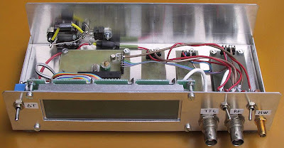
There are 3 inpust on this project a microwave (prescaled) input, an RF input and a TTL input. The microwave and RF inputs are AC coupled and terminated to a low impedance (around 50ohms). The TTL input is DC coupled and has a high input impedance. A progress-bar indicator is provided on the LCD for the gate timing.
Both the microwave and RF inputs have an additional feature : a simple signal-level detector driving yet another bar indicator on the LCD module. This is very useful to check for the correct input-signal level as well as an indicator for circuit tuning or absorption-wave-meter dip display (Lecher wires). This project designed by Matjaz Vidmar.
tag : RF counter, Microwave Frequency counter, PIC project source
Simple PIC RF/Microwave Frequency Counter

There are 3 inpust on this project a microwave (prescaled) input, an RF input and a TTL input. The microwave and RF inputs are AC coupled and terminated to a low impedance (around 50ohms). The TTL input is DC coupled and has a high input impedance. A progress-bar indicator is provided on the LCD for the gate timing.
Both the microwave and RF inputs have an additional feature : a simple signal-level detector driving yet another bar indicator on the LCD module. This is very useful to check for the correct input-signal level as well as an indicator for circuit tuning or absorption-wave-meter dip display (Lecher wires). This project designed by Matjaz Vidmar.
tag : RF counter, Microwave Frequency counter, PIC project source
Thursday, September 10, 2009
Driver Beban AC tanpa Relay
Saat kita ingin mengendalikan beban AC 220 Volt. Entah itu heater, pump ato fan. banyak dari temen2 yang memakai relay. Gak ada salahnya sich make’ relay, but I think rada mahal n makan tempat di PCB.
Sekarang mari kita coba rangkaian alternatif, menggunakan MOC3020 dan BTA12.
- MOC3020 merupakan OptoTriac, kita menggunakan device ini agar rangkaian control(microcontroller, led, keypad, lcd dan kawan2..)terisolasi dengan rangkaian power. Jadi saat rangkaian power meleduk, rangkaian control tetep aman.
- BTA12, TRIAC dengan kemampuan beban maximum 12 A. Udah tau blum triac itu apa?? klo blum silahkan klik link ini
gambar di atas merupakan rangkaian driver nya.
Part list:
- MOC 3020
- R 380 ohm
- Triac BTA 12
- R1 10K ohm
- C 100 nano / 400 volt
- R2 220K ohm
Saat Logic dari micro berlogika “High” ,
arus akan mengalir dari VCC melewati R 380 ohm kemudian menuju MOC3020. Ini menyebabkan MOC3020 “ON”.
Saat MOC 3020 “ON”, maka TRIAC BTA12 akan ikut “ON”. Arus 220 AC akan melewati TRIAC dan menuju LOAD / BEBAN AC.
Sehingga beban aktif.
Sebaliknya, saat Logic dari micro “Low”, maka arus dari VCC tidak masuk ke MOC3020 tetapi akan menuju pin micro.
Ini menyebabakn MOC3020 “OFF” , BTA 12 juga akan “OFF”.
Saat BTA12 berubah dari ON ke OFF, tegangan yang masih ada di BTA12 akan menimbulkan “spike” (loncatan tegangan).
Spike jika pada relay berupa loncatan bunga api.
Spike ini akan memperpendek umur BTA 12.
Nah, makanya rangkaian ini dilengkapi dengan kombinsai R1 dan C. Kombinasi R1 dan C ini disebut rangkaian snubber
R2 digunakan untuk membuang muatan tegangan yang ada di Capasitor saat BTA12 “OFF” .
Jika R2 tidak di pasang, saat BTA12 “OFF”. Capasitor akan terus menerus menyimpan muatan. Ini akan merusak Capasitor.
Seingetku saat memakai rangkaian ini untuk aplikasi heater, jika tidak memakai R2 maka dalam 1*24 jam. Capasitor akan short.
NB:
- Rangkaian di atas tidak mutlak harus memakai MOC3020. Tapi bisa juga memakai MOC3021, MOC3022 atau MOC3030
- TRIAC nya juga bisa di ganti BTA16. Klo BTA16 berarti maximum arus menjadi 16 Ampere
- Dari pengalaman, jika gak memakai rangkaian snubber, kadang2 beban bisa tiba2 nyala n tiba2 mati padahal belum ada perintah dari micro. Dugaan awal ini pengaruh dari spike
Mohon kritik dan sarannya ^_^ n posting comment di blog ini http://avrku.blogspot.com Trims…
any question??? send email to zigan@ymail.com
Monday, September 7, 2009
Smartphone AVR DTMF Remote Control
This project based on Microcontroller AVR ATtiny 2313 and SmartPhone as main part. The project can controls 3 relays by DTMF sounds emitted by a Smartphone. Emilio, the designer, said that this project useful for controlling, for example a rover, using relay as motor power switches.
The Smartphone (with Windows Mobile 6 OS) can run as web server with capture ability and send the picture to the client via internet. Other features of this circuit is the Smartphone can also moved and controlling motors with his speaker, emitting the correct dial tones in relation to GET requests from internet client. It's not necessary to make any connection from the phone to the circuit, because the phone connects "wireless" using the sound.
You can download test program written for smartphone WM6, schematic, and hex file here
Tag: DTMF Remote, Smartphone, Wireless Remote, Remote control, AVR project
Smartphone AVR DTMF Remote Control
This project based on Microcontroller AVR ATtiny 2313 and SmartPhone as main part. The project can controls 3 relays by DTMF sounds emitted by a Smartphone. Emilio, the designer, said that this project useful for controlling, for example a rover, using relay as motor power switches.
The Smartphone (with Windows Mobile 6 OS) can run as web server with capture ability and send the picture to the client via internet. Other features of this circuit is the Smartphone can also moved and controlling motors with his speaker, emitting the correct dial tones in relation to GET requests from internet client. It's not necessary to make any connection from the phone to the circuit, because the phone connects "wireless" using the sound.
You can download test program written for smartphone WM6, schematic, and hex file here
Tag: DTMF Remote, Smartphone, Wireless Remote, Remote control, AVR project
Sunday, August 30, 2009
AVR Shark Tag Project
The project used the Atmel Mega32 microcontroller to develop the core platform and functionality of a data archival tag. The project use temperature and pressure as sensor variable. The tasks ranged from logging sensor data to developing a simple user interface that requires only the addition of a laptop and a custom RS232 serial cable in the field.
It used an off-the-shelf SD (Secure Digital) card using flash memory for large capacity multi-read/write data storage. The microcontroller’s ADCs (analog to digital converters) were used to convert analog voltages produced by select sensors into digital format.
Tag: Animal Tag, shark, data logging, avr project src
AVR Shark Tag Project
The project used the Atmel Mega32 microcontroller to develop the core platform and functionality of a data archival tag. The project use temperature and pressure as sensor variable. The tasks ranged from logging sensor data to developing a simple user interface that requires only the addition of a laptop and a custom RS232 serial cable in the field.
It used an off-the-shelf SD (Secure Digital) card using flash memory for large capacity multi-read/write data storage. The microcontroller’s ADCs (analog to digital converters) were used to convert analog voltages produced by select sensors into digital format.
Tag: Animal Tag, shark, data logging, avr project src
Saturday, August 29, 2009
USB AVR ISP downloader
Dari judul nya pasti semua dah pada ngiler pengen nyoba nih project.. he3…,
YUpz,,, kita akan coba bikin USB downloader buat Atmel AVR microcontroller..
Firmware, Schematic n Driver project nih ak dapet dari temenku Achmad Fiqhi (meet him on FaceBook: vik_ah@yahoo.co.id).
Dia dah nyoba alat ini, n lancar2 aja. Budget yang dia kluarin skitar 50 ribu, jauh lebih murah ketimbang beli USB Downloader yang harganya rata2 diatas 150rb. Makasih banget pokoknya buat temen yg satu ini dah mau bagi2 ilmunya.
Project ini berbasis ATmega48 tapi bisa juga pake’ ATmega8. Yang perlu diinget Firmware nya harus tepat. Di akhir atikel ini kita sudah sertain file2 yang berhubungan dengan project ini,
- Rangkaian Schematic
- Firmware
- Driver
- AVRdude
Rangkaian Schematic
buka folder “circuit”
buka file USBasp.sch menggunakan software PCB maker seperti EAGLE
dalam file sch ini terdapat contoh rangkaian yang menggunakan ATmega48.
temen2 bisa mengganti ATmega48 ini dengan ATmega8
Firmware
buka folder “../bin/firmware”
disini terdapat file usbasp.atmega48.xxxx-xx-xx.hex (gunakan file ini jika menggunakan ATmega48)
dan
usbasp.atmega8.xxxx-xx-xx.hex (gunakan file ini jika menggunakan ATmega8)
untuk memasukkan firmware awal maka kita harus menggunakan downloder laen yang dah jadi seperti DT-HiQ AVR ISP nya innovativeelectronics.com ato downloader USB nya klinik-robot.com .dll…
ingat… set jumper J2 saat mengisikan firmware
Driver
begitu Firmware dah dimasukin ke micro, berarti USBdownloader kita dah siap pake… tinggal colokin ke PC..
saa dicolokin maka windows akad detect nih sebagai “new hardware” n butuh driver.
Nah drivernya ada di "bin/win-driver".
trus windows pasti bilang klo nih hardware “not digitally signed… n bla bla bla…….” pilih continue anyway.
AVRdude
Yooww sekarang kita bisa memasukkan program ke Atmel AVR microcontroller menggunakan USBdownloader kita.
Untuk memasukkan nya kita memakai software AVRdude.
caranya:
klik build.bat ato mega8.bat
pokoknya file “.bat” di dalam folder “.. bin/firmware“ (folder tempat “avrdude.exe”)
lalu akan muncul commandprompt (jendela layar hitam)
ketik:
avrdude -c usbasp -p atmega8535 -U flash:w:main.hex
untuk memasukkan program main.hex ke mikro ATmega8535
NB:
- FIRMWARE adalah program yg ada pada microcontroller sebuah sistem. Suatu sistem berbasis microcontroller tentu gak akan jalan jika micro nya gk di program.. nah program di dalam mikro ini namannya firmware
Jumper2 pada USBdownloader ini adalah:
- J1 (supply power target). Target bisa menggunakan supply +5V dari PC dengan men-set jumper ini. HATI-HATI saat menggunakan jumper ini karena jika target board short circuit resiko nya PC/laptop kita.
- J2 (update firmware). Set saat mengisi awal atau mengganti program /firmware yg ada pada micro di USBdownloader ini. Penggantian firmware dengan bantuan Downloader yg laen
- J3 (SCK option). Jika clock target di bawah 1,5MHZ maka jumper ini harus di set. sehingga SCK akan diturunkan dari 375KHz menjadi 8KHz
Download Firmware , Schematic dan Driver project ini di:
Server Indonesia:
http://www.indowebster.com/USBaspFile.html
Foreign Server:
- USBasp .......................... http://www.fischl.de/usbasp/
- Firmware-only AVR USB driver .... http://www.obdev.at/products/avrusb/
avrdude ......................... http://www.nongnu.org/avrdude/
libusb .......................... http://libusb.sourceforge.net/
libusb-win32 .................... http://libusb-win32.sourceforge.net/ - 2007-07-23 Thomas Fischl <tfischl@gmx.de>
http://www.fischl.de
Mohon kritik dan sarannya ^_^ n post comment di blog ini. Trims…
any question??? send email to zigan@ymail.com
Sunday, August 2, 2009
PIC Cactus LED Display
LEDactus is LED display project that resemble Cactus. It used PIC microcontroller 18F1320 as controller of the LED. LEDactus is immobile and attempts to survive by creating a pleasant display. It can produce more complex and mesmerizing displays. And in the latest generations, a sense of touch is added to allow the LEDactus to interact with passersby.
term : LED display, electronic cactus, PIC project (src)
PIC Cactus LED Display
LEDactus is LED display project that resemble Cactus. It used PIC microcontroller 18F1320 as controller of the LED. LEDactus is immobile and attempts to survive by creating a pleasant display. It can produce more complex and mesmerizing displays. And in the latest generations, a sense of touch is added to allow the LEDactus to interact with passersby.
term : LED display, electronic cactus, PIC project (src)
Monday, July 13, 2009
One Motor Walker Robot Without uC
Robot is interesting electronic project. We often see that robot project need a microcontroller as main processor. But if you don't have any programming skill yet, don't worry, you can build one motor walker robot by Jerome Demers. Yes the it's a walker robot without a microcontroller. The robot is base on the principal of B.E.A.M robotics! Building simple and elegant robot inspired by insect.
See the robot in action
via circuitlake
One Motor Walker Robot Without uC
Robot is interesting electronic project. We often see that robot project need a microcontroller as main processor. But if you don't have any programming skill yet, don't worry, you can build one motor walker robot by Jerome Demers. Yes the it's a walker robot without a microcontroller. The robot is base on the principal of B.E.A.M robotics! Building simple and elegant robot inspired by insect.
See the robot in action
via circuitlake
Tuesday, June 30, 2009
PIC LCD Oscilloscope for Spectrum Analyzers

This is simple and inexpensive LCD oscilloscope for spectrum analyzer display. The project use PIC 16F876A as main processor. Although a small LCD screen is not as good as analog oscilloscope, a LCD oscilloscope may be very useful in field measurements, for battery operation or you need different measurement at the same time along with oscilloscope.
The 80dB scale of this LCD oscilloscope can be adjusted with the two trimmers providing the reference voltages to the A/D converter. The operation of the LCD oscilloscope is slightly different between the 80dB mode and the 40dB mode. In the 80dB mode, the trace is always visible and saturates on the bottom or top of screen. In the 40dB mode, the trace runs out of the screen and only the central part of the original 80dB scale is displayed. This project designed by Matjaz Vidmar.
Download
Source code, documentation and schematic
tags : LCD, Oscilloscope, Spectrum Analyzer, PIC, microcontroller, project src
PIC LCD Oscilloscope for Spectrum Analyzers

This is simple and inexpensive LCD oscilloscope for spectrum analyzer display. The project use PIC 16F876A as main processor. Although a small LCD screen is not as good as analog oscilloscope, a LCD oscilloscope may be very useful in field measurements, for battery operation or you need different measurement at the same time along with oscilloscope.
The 80dB scale of this LCD oscilloscope can be adjusted with the two trimmers providing the reference voltages to the A/D converter. The operation of the LCD oscilloscope is slightly different between the 80dB mode and the 40dB mode. In the 80dB mode, the trace is always visible and saturates on the bottom or top of screen. In the 40dB mode, the trace runs out of the screen and only the central part of the original 80dB scale is displayed. This project designed by Matjaz Vidmar.
Download
Source code, documentation and schematic
tags : LCD, Oscilloscope, Spectrum Analyzer, PIC, microcontroller, project src
Wednesday, June 24, 2009
USB PIC Programmer
Usbpicprog is an USB in circuit programmer for Microchip PIC processors. The hardware is as simple. The latest version only contains one PIC18F2550, 3 mosfets, and besides the connectors a hand full of passive components.
download
Open source programmer