Wednesday, September 30, 2009

Sharp NetWalker PC-Z1 unboxing and hands-on


Click to see the video


Some more first impressions:

- I'm not liking the keyboard at all.. key caps bend to all directions.

- touch screen got better by cleaning it fully ( there was traces of screen cover glue )

- after i calibrated the screen it is accurate and easy to use ( u need to turn it off and on to save the calibrations )

- I adjusted the font sizes bigger for easier use

- mouse is ok

- surfing with it is sometimes ok, sometimes too slow

- battery life seems good.. no real numbers yet but it could be about 7 hours on full use


I will test it more and will try to get flash and youtube working ( there should be a patch for that )

... soon we will have nice "Atom vs ARM" on UMPC battle..


Thanks again Conics for sending me it!


Get yours from Conics.net
[ click video tab to see how to set it to English ]

Details, News and Links for Netwalker

Tuesday, September 29, 2009

C-motech to make Snap Dragon tablet, Mangrove


Click here to see more


Yep, more and more tablets coming..

Known specs on C-motech's tablet :

7 inch touchscreen
Qualcomm Snap Dragon
Wireles options ( wifi, 3G, wimax )
2 * USB
Micro SD
Headset port
Windows Mobile 6.5


Via Aving.net [ translated ]

http://www.cmotech.com/

Monday, September 28, 2009

Meet Hanvon multitouch tablet


Click to see the video


No other specs yet, but we should get them soon..

Thanks Xavier!


Remote Control using PIC16F84A Microcontroller

Remote Control using PIC16F84A Microcontroller


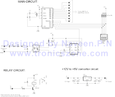
design controls up to 8 devices using a PIC microcontroller (PIC16F84A) connected to the phone line. The unique feature here is that unlike other telephone line based remote control, this device does not need the call to be answered at the remote end so the call will not be charged. This device depends on number of rings given on the telephone line to activate/deactivate devices.

1. Circuit diagram (designed by www.tronicszone.com)
2. Parts List
3. C source code complied using HT-Soft PIC C compiler
4. Compiler Hex code file to be directly programmed into the PIC

Instructions for the telephone operated remote switch:

A) While constructing the main circuit, make sure you use 18pin sockets (base) for the PIC16F84A. Do not solder the IC directly to the board since you may have to remove it for programming. Before you use the PIC on the main circuit, you have to first program it.

B) To program the PIC16F84A microcontroller:

There are lots of programmers on the Internet available to program PIC microncontrollers. Given below are links to some free PIC programmer hardware/software:

* http://www.covingtoninnovations.com/noppp/
* http://www.picallw.com/
* http://www.lpilsley.uklinux.net/software.htm

Note: Programm the chip with the hex file attached above and remember to set the fuse bits to use "EXTERNAL HS OSCILLATOR" mode!

C) Remove the PIC from the programmer socket and put it into the main circuit socket.

Set the DIP SWITCH as follows:

Switch3 Switch4 No. of initial rings to Switch ON(activate half of the board)

OFF OFF 5

ON OFF 4

OFF ON 3

ON ON 2

The number of initial rings to Switch OFF is one more than the number of rings to switch ON. For example, if you have set switch3 OFF & Switch4 ON then number of initial rings to activate half of the board to switch ON the relays is 3 and number of initial rings to activate half of the board to switch OFF the relays is 3+1 = 4

Switch1 Swtich2 Delay before making the second set of rings

OFF OFF 20sec

ON OFF 15sec

OFF ON 10sec

ON ON 5sec

This is the maximum delay the board can take after it is half activated. It will reset after this delay.

D) Now connect the circuit to the phone line and switch on its power supply.

E) You can test the board now. For example set the DIP switch to Switch1 ON, Switch2 OFF (15 sec delay) & switch3 ON, switch4 OFF (4 rings to activate half for switching ON). If you want to switch ON relay 1 (connected to RB0 of main circuit) then you have to do the following:

1. Give 4 rings and put down the receiver
2. Wait 5 seconds (this 5 seconds wait is required to prevent the board from detecting continous rings)
3. then within 15 seconds give 1 ring (1 ring for relay1, 2 rings for relay2 and so on) and put down the receiver
4. then within 5 sec the relay1 will switch ON

To switch off relay1:

1. Give 5 rings and put down the receiver
2. Wait 5 seconds (this 5 seconds wait is required to prevent the board from detecting continous rings)
3. then within 15 seconds give 1 ring (1 ring for relay1, 2 rings for relay2 and so on) and put down the receiver
4. then within 5 sec the relay1 will switch OFF

IMPORTANT: This circuit has been tested by me and found to work correctly. I cannot guarantee that the circuit will work at your end since it depends on error free construction and usage. Please do not contact for any support and requests, any such requests will not be entertained.

Rangkaian Generator IF Sederhana

Rangkaian Generator IF Sederhana


A versatile circuit of IF signal generator which may be of interest to radio hobbyists and professionals alike.Transistors T1 and T2 form an astable multivibrator oscillating in the audio frequency range of 1 to 2 kHz. RF oscillator is built around transistor T3. Here again a 455kHz ceramic filter/resonator is employed for obtaining stable IF. The AF from multivibrator is coupled from collector of transistor T2 to emitter of transistor T3 through capacitor C3. The tank circuit at collector of transistor T3 is formed using medium wave oscillator coil of transistor radio, a fixed 100pF capacitor C5 and half section of a gang capacitor (C6).


The oscillator section may be easily modified for any other intermediate frequency by using ceramic filter or resonator of that frequency and by making appropriate changes in the tank circuit at collector of transistor T3. Slight adjustment of bias can be affected by varying values of resistors R6 and R7, if required

Rangkaian Simple Analog to Digital Converter

Rangkaian Simple Analog to Digital Converter

Normally analogue-to-digital con-verter (ADC) needs interfacing through a chip to catechumen alternation abstracts into agenda format. This requires accouterments and all-important software, consistent in added complication and appropriately the absolute cost.

The ambit of A-to-D advocate apparent actuality is configured about ADC 0808, alienated the use of a microprocessor. The ADC 0808 is an 8-bit A-to-D converter, accepting abstracts curve D0-D7. It works on the assumption of alternating approximation. It has a absolute of eight alternation ascribe channels, out of which any one can be called application abode curve A, B and C. Here, in this case, ascribe approach IN0 is called by accomplishments A, B and C abode lines.

Usually the ascendancy signals EOC (end of conversion), SC (start conversion), ALE (address latch enable) and OE (output enable) are interfaced by agency of a microprocessor. However, the ambit apparent actuality is congenital to accomplish in its affiliated approach afterwards application any microprocessor. Therefore the ascribe ascendancy signals ALE and OE, actuality active-high, are angry to Vcc (+5 volts). The ascribe ascendancy arresting SC, actuality active-low, initiates alpha of about-face at falling bend of the pulse, admitting the achievement arresting EOC becomes aerial afterwards achievement of digitisation. This EOC achievement is accompanying to SC input, area falling bend of EOC achievement acts as SC ascribe to absolute the ADC to alpha the conversion.

As the about-face starts, EOC arresting goes high. At abutting alarm beating EOC achievement afresh goes low, and appropriately SC is enabled to alpha the abutting conversion. Thus, it provides affiliated 8-bit agenda achievement agnate to direct amount of alternation input. The best akin of alternation ascribe voltage should be appropriately scaled bottomward beneath absolute advertence (+5V) level.

The ADC 0808 IC requires alarm arresting of about 550 kHz, which can be calmly acquired from an astable multivibrator complete application 7404 inverter gates. In adjustment to visualise the agenda output, the row of eight LEDs (LED1 through LED8) accept been used, wherein anniversary LED is affiliated to corresponding abstracts curve D0 through D7. Since ADC works in the affiliated mode, it displays agenda achievement as anon as alternation ascribe is applied. The decimal agnate agenda achievement amount D for a accustomed alternation ascribe voltage Vin can be affected from the relationship


Skema Rangkaian Seven Segment

Skema Rangkaian Seven Segment

It is actual absorbing and acceptable to be able to ascendancy aggregate while sitting at your PC terminal. Here, a simple accouterments ambit and software is acclimated to interface a 7-segment based rolling display. The printer anchorage of a PC provides a set of credibility with some acting as ascribe curve and some others as achievement lines. Some curve are accessible beneficiary blazon which can be acclimated as ascribe lines. The ambit accustomed actuality can be acclimated for interfacing with any blazon of PC’s printer port. The 25-pin alongside anchorage adapter at the aback of a PC is a aggregate of three ports. The abode varies from 378H-37AH. The 7 curve of anchorage 378H (pins 2 through 8) are acclimated in this ambit to achievement the cipher for articulation affectation through IC1. The actual one band of anchorage 378H (pin 9) and four curve of anchorage 37AH (pins 1, 14, 16, 17) are acclimated to accredit the affectation digits (one a time) through IC2. The $.25 D0, D1 and D3 of anchorage 37AH affiliated to pins 1, 14 and 17 of ‘D’ adapter are astern by the computer afore appliance to the pins while abstracts bit D2 is not inverted. Therefore to get a argumentation aerial at any of aloft three pins, we charge accelerate argumentation 0 achievement to the agnate pin of anchorage 37AH. Another important abstraction illustrated by the activity is the time analysis multiplexing. Agenda that all the bristles 7-segment displays allotment a accepted abstracts bus. The PC places the 7-segment cipher for the aboriginal digit/character on the abstracts bus and enables alone the aboriginal 7-segment display. After adjournment of a few milliseconds, the 7-segment cipher for the digit/character is replaced by that of the abutting charter/digit, but this time alone additional affectation chiffre is enabled. After the affectation of all characters/digits in this way, the aeon repeats itself over and over again. Because of this alliteration at a adequately aerial rate, there is an apparition that all the digits/characters are continuously actuality displayed. DISP1 is to be physically placed as the atomic cogent digit. IC1 (74LS244) is an octal absorber which is primarily acclimated to access the alive capability. It has two groups of four buffers with non-inverted tri-state outputs. The absorber is controlled by two alive low accredit lines. IC2 (75492) can drive a best of six 7-segment displays. (For alive up to seven common-cathode displays one may use ULN2003 declared abroad in this section.) The affairs for rolling affectation is accustomed in the advertisement DISP.C above. Whatever the message/characters to be displayed (here bristles characters accept been displayed), these are afar and stored in an array. Then these are decoded. Decoding software is actual simple. Just alter the adapted appearance with the bifold agnate of the affectation code. The affectation cipher is a byte that has the adapted $.25 angry on. For example, to affectation appearance ‘L’, the segments to be angry on are f, e and d. This is agnate to 111000 bifold or 38 hex. Please agenda that alone bound characters can be formed application 7-segment display. Characters such as M, N and K cannot be formed properly