Sunday, November 8, 2009

Programming Adaptor Board for FD-SPP/ICP/UPP

Introduction:

This programming Board is designed to be used with Serial, ICP and USB programmers detailed elsewhere on this site.

In view to keep cost low, board contains simple DIP sockets of 20Pin, 18Pin, 28Pin & 40Pin.

20Pin socket may be used for programming of 8pin, 14pin & 20pin PIC Micro Controllers.

18, 28 and 40pin sockets are specific to such PICs.

New PB1.2: Revised PCBs : 12th Dec 07


In my new run of PCBs, I have 20, 18, 28 and 40pin DIP sockets. I have also amended 0.1uf Tantalum capacitors by 0.1uf ceramic.

I have added LVP selector, a 4 position slide switch, for those working with Low Voltage Programming, where a pull-down is required. LVP pull-down resistor may be selected by user on Specific Chip socket for specific purpose.

Interface to ART2003 Programmer:

In view to extend various PICs, hhis programming board may be used with FD-ART2003 Parallel Port Programmer detailed elsewhere. However, you will have to do external wiring between two boards yourself.

Serial & ICP Programmers:

This board is 100% compatible with FD-ICP and FD-SPP Programmers

Interface to PICKIT2:

This board is pin compatible with PICKIT2 & PICKIT2 USB programmers. You may use this programming board to program 8, 12, 18, 20, 28 & 40 pin PIC Micro Controllers.

Picture of the Programming Adaptor Board: PB1.2


Parallel Port Programmer for PIC 18Fxxx

FD-ART2003

Developed specifically for programming of PIC 18F2550 micro controllers, this parallel port, no-power, programmer is the smallest of all programmers ever built.

A DB25 Male Connector, one capacitor and a resistor makes this Port Powered programmer.

Programmer takes its power from Parallel Port pins 2-9. VPP for this programmer is 5V and hence "LVP" must be selected in programming software. (See art2003 screen shot Document given below)

I built this programmer to write firmware (boot loader) into my PIC18F2550 which I wanted for my PICKIT2 inspired USB programmer.

A free windows based program called WINPIC800 V.3.59 is available for free download. This software is not intended for this programmer alone, you may use it for many other programmers including few detailed here on this website.

Although, programmer socket is wired for PIC18F250 & 2550, other PICs with similar pin connections may be programmed. You may also wire your own socket for different type of PIC if the same is supported in the WINPIC800 (under Art2003 selection).

And there is always a possibility to use Programming Adaptor board wired to this programmer to get larger acceptance of various PICs.

This programmer is designed on a 6cm X 4cm Doubled Sided PTH Board.

Picture of the PIC 18Fxxx Parallel Port PIC Programmer


Parallel Port ICP PIC Programmer - FD-ICP

Introduction: FD-ICP

In addition to Simple Parallel port PIC Programmer detailed elsewhere on this site, I wanted a Parallel port PIC Programmer with ICP output socket. This project came to my mind from a concept by OziPic’er.

This programmer is built for Free Windows Software called WinPicProg developed by Nigel Goodwin and uses a 74HC14 instead of 74LS05 used on other parallel port programmers.

Programmer PCB is double sided PTH board, 6CM X 8CM and has a 6 Pin Female ICP output connector with pin connections exactly same as PICKIT2 of Microchip.

An adaptor suitable for 8, 14, 18, 20, 28 & 40 Pin PIC Micro Controllers is available to use with this ICP Programmer.

It should be noted that even though, all kind of PIC Micro Controllers may be accepted by Adaptor board, only those supported by software might be programmed.

Hardware:

You require a 12-18V AC or 14-18VDC power supply. When connected, an LED labeled, as “Power” will light. Indicates that 13.2V is now available on board. This is Vpp supply used for programming.

Run WINPICProg software on your PC to check out if rest of the hardware is functioning well. Vdd LED will light when Vdd (Target Power) check box is ticked on software window. Similarly, Vpp lights may be tested by selecting appropriate devices.

Although, Vpp & Vpp2 are generated separately by software, they are combined within the hardware to produce a single Vpp for ICP connector. Q6 is used for Vpp reset.

Compatibility with OS:

This is a Parallel Port PIC programmer and is duly tested on Win98. If you decide to make or buy this programmer and want it to use with XP/Vista etc, please ensure that you understand your OS very well. I wont be in a position to support for questions related to Port configuration etc for specific OS. For XP/Vista etc please look for a suitable USB PIC Programmer.

Picture of the Parallel Port ICP PIC Programmer

PIC ICP PROGRAMMER BY FOX DELTA


Adaptor Board:

This board is required if you wish to program PIC Micro Processors not fitted in circuit boards already.

On this board we have different sockets to accommodate various types of PICs.

Picture of the Programming Adaptor Board


Serial Port PIC Programmer for PIC16 & PIC18

Model: FD-SPP

PIC Programmer is an essential tool if you wish to learn or build projects with Microchip PIC Micro Processors.

This programmer is for those who do not have a Parallel Port on their PC. Programmer may be used with Free Windows Software such as "PIC PROGRAMMER Professional Serial" from Oshosoft and may work well with other serial programming software.

Programmer PCB is double sided PTH board measuring 6cm X 8cm. Since my idea was to make this programmer small in size with ICP capability with ICP header having PICKIT2 compatible pin connections, I have used a separate Programming Board containing IC sockets for 20 (Includes 8,14 & 20 pin PICs), 18, 28 & 40 pin PICs.

Firmware in PIC 16F628A controls TXD, RXD, Vdd & Vpp lines to program the Target Chip. A true RS232 interface IC is used to connect programmer to PC's com port.

To use this Programmer, you will require a 14-20V DC or AC Power adaptor, A Programming Adaptor Board and a serial cable. Programming Adaptor Board is included with this programmer.

If you wish to build this programmer using your own parts, you may buy a PCB for this project.

PCB with Pre-programmed firmware in PIC 16F628A is also available for those who do not have a programmer.

If wish to build this programmer using PIC16F628A, 627, 627A or 628, you may request for a suitable firmware with 8, 10, 12, 16 or 20MHZ crystal frequency.

Free firmware for PIC16F628 & 628A is already supplied here for crystal frequencies of 8, 10, 12, 16 & 20MHZ.

Free Serial Port Prof Programming Software is suitable for programming, both PIC16F & PIC18F chips, using this programmer.


Picture of the Serial Port PIC Programmer

Fox Delta Professional PIC Programmer FD-SPP


Picture of the Complete Programmer assembled

FD-SPP with PB1

Parallel Port Microchip PIC Micro Controller Programmer

PIC Programmer is an essential tool if you wish to learn or build projects with Microchip PIC Micro Processors.

This programmer is built using Free Windows Software called WinPicProg and other similar software from PICALLW or Oshosoft

Programmer PCB is double sided PTH board. In this programmer, you have a 0.3 Inch IC socket (40pin) on the main board, where you can place either 8, 18 or 28pin ICS for programming. An adaptor PCB with male/Female header is supplied with this kit for 40pin DIP. (without 40pin DIL Socket)

However, make sure that you insert PIC ICs at the proper location on this 40Pin socket. Suitable markings of placement are made on the PCB.

I have included required hardware settings in the DOC for Oshonsoft parallel programming software

Warning: This programmer is controlled from Parallel Printer Port of your PC.
If you keep Micro-controller chip on this powered programmer & try to PRINT from any application, it would damage the micro-controller. Apply power to this programmer only after running the programming software.

Picture of the PIC Programmer KIT with Standard Socket:


To use this programmer, all you require is 12-18V AC Adaptor and a cable to connect to the parallel port of your computer.

PICKIT2 Compatible USB PIC Programmer

Introduction: FD-UPP

PIC Programmer is an essential tool if you wish to learn or build a project that uses Microchip PIC Micro Processors such as DDS, Repeater Controllers and LCD Power Meter.

This programmer is built around Microchip’s PICKIT2 programmer, which is basically a surface mount, fully assembled, ready to use product. It’s called a “Kit” but it is not!! This one is a true kit for radio amateurs.

Benefit of making PICKIT based programmer for amateur radio is further supported by freely downloadable PICKIT2 software for windows. Microchip keeps this software updated for new devices that they launch.

In this project, to make it simple, I have removed the voltage level change capability of firmware for VDD 3V. Means, this programmer will only program 5V PIC Micros.

Project uses a PIC16F2550 in 28pin DIP package. All diodes are standard lead type & FETs are either in TO92 or HEXDIP packages, to make assembly smooth & easy.

Kit is supplied with FD-PB1 Programming board. PB1 uses standard IC Sockets for 40, 28, 8,14, 20 & 18PIN DIP PIC Micros.

In view to make a suitable metal case for this programmer, FD-UPP has two headers H1 & H2, which will be used by “piggy back” Programming board I will design later.


Adaptor Board:

FD-UPP KIT includes PB1, a simple programming adepter board.
On this board we have different sockets to accommodate various types of PICs. It accepts 8, 14, 18, 20, 28 and 40 PIN DIP PIC Micro Controllers.


Monday, November 2, 2009

How to program Microchip PIC microcontrollers

This is something I learned to do fairly recently (6 months ago) on my Mac, after looking for the correct tools for a long time (like a whole year before that). Granted, I have been able to program PICs with my PC for 2 years through the "official" methods, and with a little help from the existing virtualization options.

But today I want to describe how to do it in the Macintosh, 100% no emulation, no virtualization.

First, you will need is a Pickit-1 like mine. They are dirt cheap these days, like $36 direct from Microchip.

After ordering the Pickit, you can get free samples from the company's website. Be sure to check the PIC compatibity within the Pickit-1. I ordered a bunch of 16F675 because they are the only supported PICs with hardware UARTs in them.
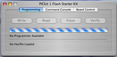
Second, obtain a copy of Microchip OSX Pickit tool. It comes with no official support, but it is open source. Get a copy here: Intel, PPC. Use the OSX tool to test that you can download the .HEX files included in the CDROM.


Congratulations. Now you can program PIC microcontrollers!

Of course, you will need a compiled/assembled HEX file to flash your PIC now. There are many, many ways of achieving this, and the ways are more numerous with VPC/Parallels/Bootcamp, but I am working on another blog post that will describe how to code the PIC within OS X.